
A client approached me with a need to produce an animation in Line Drawing format. I didn’t understand what they meant. They meant that all shapes are simply oulined, and the shapes themselves have no materials assigned to them. In fact, the entire environment (background) was to be the same color as all the objects, giving the scene a floating kind of look as the camera circled the scene.
This seemed to be really hard! How could I disable shadows, shading, radiosity-everything-and still make the shapes discernable? The more I thought about it, the more possibilities arose. Unfortunately, 3ds Max gives the user more than one way to do somethnig-often many more. I wanted to find the easiest way to do it.
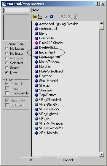
The answer came from, as usual, a feature I seldom use. In this case the Ink ‘n Paint material combined with another feature at the bottom of certain object rollouts: Smoothing Groups.
But it isn’t as simple as that. There is more than one way to draw an object. Lets take a look at 3 examples of the same object rendered 3 different ways-each technically still a line drawing (click on any picture for a 100% zoom):
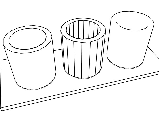
The three images above are all the exact same object, with no modifications whatsoever in their geometry. They even have the same material. What sets them apart is one of the last things learned about 3ds-Smoothing Groups.
You have the Smoothing Groups group available whenever you elect a sub-object mode (Vertex, Edge, etc.) from an editable Mesh, Poly or Patch. Editable Splines don’t have smoothing groups because they don’t have faces. In other words-theres nothing to smooth. This is also the case for splines converted to NURBS. This isn’t the case, obviously, if you turn your spline into an editable Mesh, Poly or Patch, as it will then have faces to smooth.
Smoothing Groups
Smoothing Groups do not affect geometry. They affect how the joints (edges) between 2 polygons appear, though. Like the name implies, those edges will appear smooth where they are actually at a sharp angle. Above, the actual number that can assign smoothing groups (1 to 32) is arbitrary. A single face can be a member of as few as 0 smoothing groups, and as many as 32. While smoothing groups are normally used to give the illusion of smooth geometry without increasing the poly count, they can also be used to restrict where a material like “Ink ‘n Paint”, well, paints.
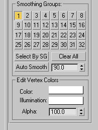
There are are at most 5 sections of the Smoothing Groups group:
1. Smoothing Group ID: The actual group # (1-32)
2. Select By SG: A requester comes up that gives a choice of the currently used group #s. You can select one or more of the groups, which in turn selects all the pertinent faces on the object. For example, if you select 3, all faces with smoothing group 3 will be selected.
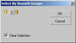
In this case, we want to have all faces that belong to smoothing groups 1 & 3 to be selected. Once selected, they can be modified as desired.
3. Clear All For the faces selected (can include the entire object), deselect, or clear, any smoothing group assignments. Its obvious to see where there is no smoothing because the edges between non-smoothed faces are sharp and not smooth (makes sense, eh?).
4. Auto Smooth: This is really useful:
As you know, every face (that has an adjoining face) has an edge between them. That edge describes an axis by which the 2 faces rotate. There is alwyas an angle defining the relationship between the 2 faces about that axis. If the 2 faces are lined up flat, that angle is 0 degrees. If they are at right angles to each other, that angle is 90 degrees.
Auto Smooth will create smoothing groups based on the angles described above within the currently selected faces. If the angle between the 2 selected faces in question is less than or equal to the number in the next field, they will be smoothed.
5. Auto Smooth Threshold: In the case of using #4 above (Auto Smooth), this is where you enter the number that will determine which faces are smoothed with each other. We’ll mess with that a little later.
Note: An Editable Patch does not provide the “Auto Smooth” option.
Ink ‘n Paint Material
Surprisingly, you don’t need to alter the material at all from its original state in order to achieve this effect. I would, however, suggest changing the Lighted color inside the material, found at: Paint Controls -> Paint -> Lighted color selector. Below is how I have the only material used:
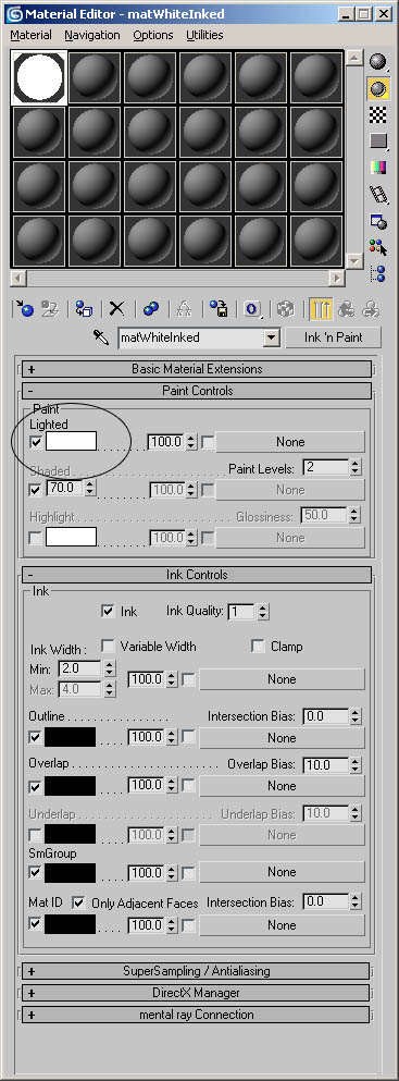
An “Ink ‘n Pain” material will cover areas within individual smoothing groups-this is why understanding smoothing groups is so important. To demonstrate this, take a look at how each of the 3 tubes you saw at the beginning was created, and what they look like in a 3ds Max viewport:
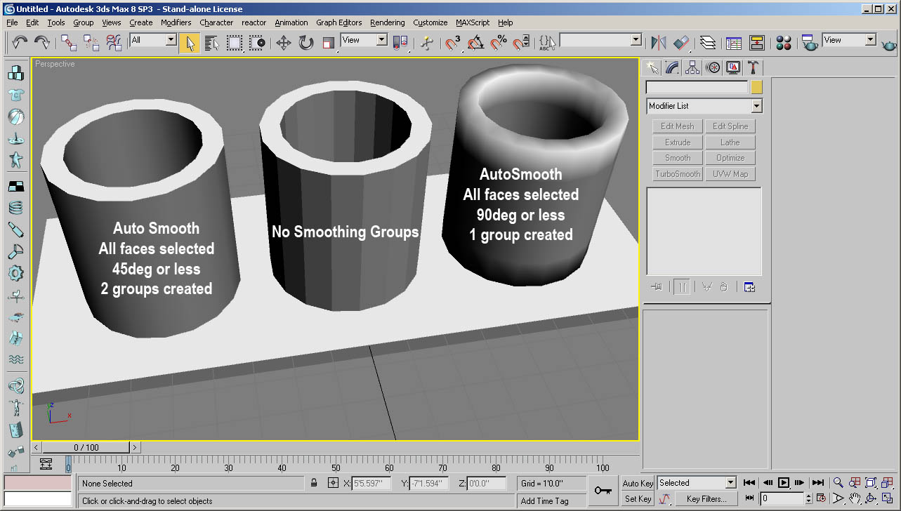
Tube01
Like all 3 tubes, this one is a primitive tube converted to an Editable Mesh. There are 2 smoothing groups created: one for the sides (as they are less than 45 degrees from each other, per the 45 degree default setting on Auto Smooth), and one for the ends of the tube, which are exactly 90 degrees from each, and all, side faces.
If you take a close look at the base, or bottom, of each of the 3 tubes, you’ll notice that although they have varying levels of smoothing on the faces that are not along the outer edges, the outer edges of each tube are the same. That is because like we said earlier, the actual geometry of the tubes is not altered by smoothing. Think of it like the how the Smooth modifier works.
Tube02
This tube has no smoothing groups applied. As expected, you can see the angles between all faces. The Ink ‘n Paint material fills all faces that are at a 0degree angle to each other. But as we’ve seen, this changes when there are common smoothing groups among adjacent faces.
Tube03
This is a great effect in some cases, where only the outer edges need to be outlined with the material. We covered the entire object with one smoothing group, but how?
We already saw that trying to do so with Tube01 didn’t work with the Auto Smooth threshold set to the default 45 degrees. What was done differently was that we changed the Auto Smooth Threshold to 90 degrees from the default 45 degrees. This meant that the 90 degree edge at the ends of the tubes was no longer off limits to smoothing froup delineation (a border).
If you look at the top of Tube03, you’ll see that the faces on the sides are smoothed with the faces on the top, or end. If you look back to the top, labeled diagram, you can now see why the final render ended up the way it did!
There are a few settings for the Ink ‘n Paint material that can really change the way your objects look. With the following settings:
…the following scene is produced:
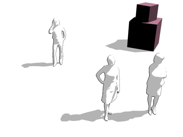
Although the client wanted everything to be white with black lines, you can add color objects, lights, and other elements to yield some interesting effects/moods.
Stay creative!
Bogus Exception


")
